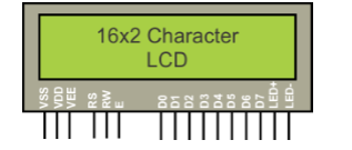
Pin configuration:
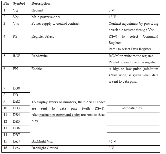
VCC, VSS and VEE:
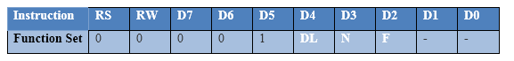
RS (REGISTER SELECT):
RW (READ/WRITE):
EN (ENABLE):
D0-D7 (DATA LINES):
THEORY FOR CUSTOM CHARACTER GENERATION:
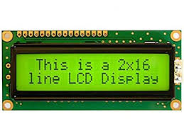
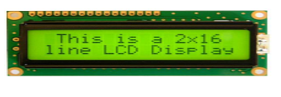
16 x 2 LCD
20 x 1 LCD
20 x 2 LCD
20 x 4 LCD
40 x 2 L CD
Description:

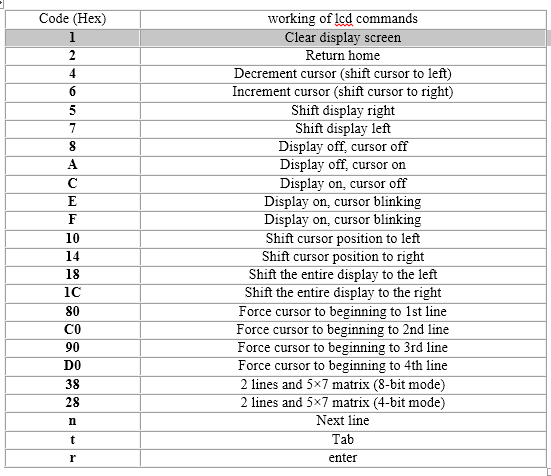
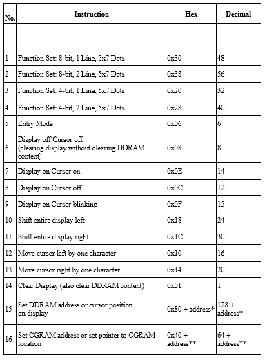
LCD COMMAND CODES:
Programming Steps:
Applications
/*  Name     : main.c
 *  Purpose  : Source code for BUZZER Interfacing with PIC18F4550.
 *  Author   : Gemicates
 *  Date     : 2017-06-12
 *  Website  : www.gemicates.org
 *  Revision : None
 */
#include <htc.h>                            // Header file for PIC18F4550
#define _XTAL_FREQ 12000000                 // 12MHZ

#define input PORTD                         // PORTD as input
#define Buzzer PORTCbits.RC0                // To set a single pin(RC0) as output


                                            // __CONFIG(PLLDIV = 5,CPUDIV = OSC1 / 2,USBDIV = 2,FOSC = HIGH_SPEED HS);
                                            // ,FCMEN = OFF,IESO = OFF,PWRT = OFF,BOR = OFF,BORV = 3,VREGEN = OFF,WDT = OFF,WDTPS = 1:32768,CCP2MX = ON,PBADEN = OFF,LPT1OSC = OFF,MCLRE = ON,STVREN = ON,LVP = ON,ICPRT = OFF,XINST = OFF,DEBUG = OFF,CP0 = OFF, CP1 = OFF, CP2 = OFF, CP3 = OFF,CPB = OFF,CPD = OFF,WRT0 = OFF, WRT1 = OFF, WRT2 = OFF, WRT3 = OFF,WRTC = OFF,WRTB = OFF,WRTD = OFF,EBTR0 = OFF, EBTR1 = OFF, EBTR2 = OFF, EBTR3 = OFF,EBTRB = OFF);
#pragma config WDT = OFF


void delay(int msec)		            // delay function
{
	int i,j;
	for(i=0;i<msec;i++)
	for(j=0;j<1275;j++);

}


void main()
{
		TRISD = 0xff;               // PORTD as output
		TRISC = 0Xfe;               // Upper bits as input and Lower bits as output.
	while(1)
	{

		switch(input)	            // Switch statement
		{

			case 0xFF:
				Buzzer = 0; // Buzzer ON condition
				break;

			case 0xFD:
				Buzzer = 1; // Buzzer OFF condition
				            // delay(100);
				            // Buzzer = 1;
			break;

                }
	}
}